
How often does this situation happen to you? The printer has printed half of the model. The model’s bottom lifts off the print bed - warping. We need to trash the whole model.
Large prints tend to warp, like furniture parts. When we make 3D-printed tools and add more wall layers to make them stronger, they sometimes warp.
You can see how warping looks and where it occurs in the image below.

In our first Bambu Lab flagstore, you can see and experience the massive CyberBrick diorama (see the image below). It simulates the futuristic city landscape. The diorama’s case is built with many identical blocks. We use it for installing a power supply system. The diorama’s base is wide and tall.

During printing, when the bottom warps, it lifts off the print bed and changes shape. This makes the surface of the printed layer get closer to the nozzle. It may cause the nozzle to scratch into the printed layer, leaving ridges and making the surface look bad.
On top of that, warping may also weaken how strongly the bottom grips the print bed. In the worst case, the print starts peeling off the print bed, causing a failure.
The left image below shows that the bottom edge curls up and changes shape. The right image below shows scratches on the surface of the curled corner. This damage causes the layer to peel off.

Like many other designers and 3D printing hobbyists, warping must have bothered you, too.
What makes warping happen?
Let’s start with the filament: the extruded filament shrinks as it cools, getting shorter. The image below shows that the filament shrinks as it cools after extrusion. The values shown are examples only. Actual shrinkage varies by filament type and print settings.

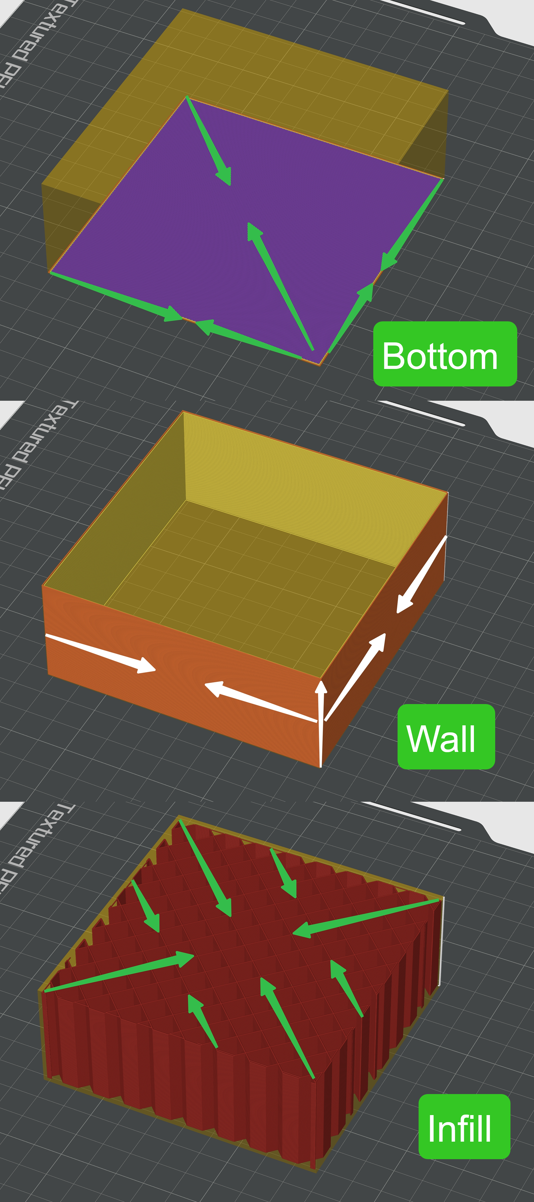
Let’s look at a cubic model now: when looking at the toolpaths, a cubic model breaks down into a top surface, a bottom, walls, and infills. They all use similar print path patterns.
The stress from shrinking usually builds up at the bottom edges as the filaments cool. You may have noticed they particularly occur on edges and corners. At these spots, the shape limits the shrinkage. This leaves limited space for the material to contract.
The stress from shrinking passes through the layers to the first layer. The first layer is in contact with the print bed. The adhesion between the first layer and the print bed works against shrinking and the shape changes it causes. When the adhesion is not strong enough to withstand stress, the bottom begins to curl up and peel off the print bed.
You can see how the bottom, the walls, and the infills tend to shrink in the image below.
We have summarised these methods to stop warping for good. We sort these methods from easy to more advanced. You can pick one and use it in your model, or mix a few for a better result.
Now, let’s have a look at the methods for fixing warping together.
Methods
To avoid warping, the easiest way is to keep the printing environment stable. Place the printer away from open windows, air vents, or frequently opened doors.
Using an enclosed printer helps trap warm air around the print, allowing it to cool more gradually. This keeps the temperature consistent and greatly reduces the chance of warping. For filaments that tend to shrink a lot, like ABS, using an enclosed printer and maintaining a consistent temperature in the enclosure are necessary.
Besides choosing a printer, let’s check out these methods to fix warping.
-
Fillet outside corners.
-
Break the model into several zones.
-
Add brims around the edges, set the print bed temperature a bit higher, and clean your build plate.
-
Change the infill pattern and density.
-
Try cool plates and liquid glues.
Fillet outside corners
As filaments cool and shrink, the model’s walls work against the stress caused by this shrinkage. The outside corners shift the most. The stress from shrinking builds up on the corners (see the image below).
From every angle, it is easy to find that warping starts at the corners. It then spreads out towards the model’s center.

Fillet the outer walls’ corners (see the left image below). This method prevents stress from building up, stopping warping and changing shape (see the right image below).

Sometimes, we need sharp corners in the model’s upper part to get a smooth surface with smaller gaps. In this case, add fillets to the sharp bottom corners. Let the rounded corners gradually turn into sharp corners towards the top (see the image below).
Set the fillet angle greater than 45 degrees to avoid overhanging tips coming off.

When the model’s top warps a bit, you may notice that the surface of the previously printed layer may get too close to the nozzle. It may also scrape the nozzle.
As such, the extruded filaments won’t be evenly placed on top of the previous layer. The excessive filaments will stack, forming blobs and ridges.
To fix this issue, we can add a pillar at each corner. The pillars stand alone and reach all the way up to the sharp corners. They help to support and secure sharp corners.
The left image below shows how these pillars look. The right image below shows that the pillar is not attached to the outer wall.

Take a close look at the highlights along the top edges of the two models in the image below.
The left model has no pillar to support its top corner. You may have noticed its top edge changes shape slightly. The corner warps a bit.
In contrast, the right model has a pillar to support its top corner. Its top edge stays uniform.

When the pillar is too thin, in Bambu Studio, you can use the Auto Brim function or draw brims manually.
Draw the brims manually, set them to 0.4mm thick, and their edges to 4mm long.
Brims help increase the contact area between the pillar bottom and the print bed. This helps them stick better. After printing, the pillars are easy to remove.
Break the model into several zones
For large parts with thick walls and solid infills, the simple changes above won’t fix the warping.
Thus, we need to modify the design. The key is to break the model into several zones. It aims to shorten the length of filament that the nozzle extrudes in a single shot.
We can use these methods to break the model into several zones:
-
Add a checker pattern to the model’s bottom
-
Add slits within the infills and to the sidewalls
-
Control the wall thickness and break continuous walls
Add a checker pattern to the model’s bottom
Add grooves to the model’s bottom to divide it into small zones, like a checker pattern (see the image below).

You can see how the print looks. Its bottom is designed with grooves. No warping appears at the corners.

This way, each small zone can bear stress on its own. You will see less warping at the corners.
Set the groove to 1 mm wide, 1 mm deep. Add a 45° chamfer to the bottom of the groove to avoid overhangs. Leave a space of 30 mm - 80 mm between grooves. (see the image below)

Add slits within the infills and to the sidewalls
When the infills are very thick, you may consider setting the slits longer (see the left image below). Longer slits help cut the infills apart. This method helps spread stress more evenly, preventing warping at the edges (see the right image below).

Please keep in mind: Cutting slits into tall parts or parts that need to bear loads makes them less strong in the vertical direction. They may tend to bend or crush easily. Thus, you can size the slits to fit your needs. In the image below, we can see that the slit sizes are adjusted based on different design needs.

We must keep their surfaces intact or ensure they do not bend when transporting or installing certain parts.
In this case, we do not need to cut the bottom. Instead, add slits to the sidewalls (see the right image below). It keeps the top and bottom intact. Or add negative parts to the model. It splits the infills into several zones (see the left image below).
They help spread stress from shrinking more evenly, preventing warping.

The image below shows how the printed model looks.

Negative parts form cavities inside the model. Please note: keep cavities more than 1 mm away from all walls. This helps prevent bridging from falling and the top from sagging.
Control the wall thickness and break continuous walls
We would add wall layers when we need to make the structure stronger or the wall of the screw hole thicker. However, thicker walls shrink more as the material cools. It makes warping worse.
The model in the right image below has more wall layers than the one in the left image below. Thus, the model with more wall layers shrinks more.

When the walls are too thick, they will shrink too much. To avoid this, keep them under 1.2 mm thick.
In some cases, we need to add wall layers to make the part stronger. If only certain areas need extra strength, use a modifier to adjust the wall layers where needed. Like the screw hole design, where we need to make the wall thicker. It may make extra work, but it helps save filaments and lowers the risk of printing failure.
The left image below shows using a modifier to adjust the screw hole’s wall layers. The right image below shows that the screw hole’s wall layers increased to 3. All other settings stay the same.

The image below shows the print result using the modifier.

In addition to controlling wall thickness, we can also design vertical grooves (along the z-axis) on the outer walls (see the image below). These grooves break the continuous wall path. The interrupted wall path helps to reduce stress on the walls.
To meet appearance needs, you can use grooves in various forms and adjust their spacing as needed (see the image below).
We can see the printed model in the right image below. Its outer walls have grooves built into the model. With this design, the walls do not change their shape.

When you need the top and bottom surfaces intact, set both to 1 mm thick and add a chamfer to the top.
A common practice is to create semi-circular grooves on the outer walls. Set the spacing between grooves to 30mm - 80mm. Keep the groove cross-section radius at 2 mm.
Add brims around the edges, set the print bed temperature a bit higher, and clean your build plate
Add brims to the bottom edges
Brims are a few lines placed around the edges of the model’s bottom (see the image below).
These lines increase the contact area between the model’s bottom and the print bed. After printing, it is easy to remove the brims.

We can add brims to corners or areas that do not stick well to the print bed. Brims are like suction cups. They increase the contact area between the model and the print bed. Brims also hold and firmly fix the corners to the print bed. They help to prevent the model from warping or peeling off (see the image below).

Source: Brim Ears. Retrieved on Mar. 02, 2026, Bambu Lab Wiki

You can add fillets to models with sharp corners. We can also use brim ears in Bambu Studio to make the corners grip the print bed even more firmly.
In Bambu Studio, when you turn on auto brim, it creates spots that generate brims at the sharp corners on the bottom edges. When the round corner is small, we can also add brims manually (see the GIF below).
See the WIKI page about Brim Ears for more information.

Set the print bed temperature a bit higher
To make the model’s bottom stick better to the print bed, try setting the print bed temperature a bit higher.
In Bambu Studio, go to Filament parameter settings > Textured PEI plate. Increase the print bed temperature by about 5~10℃. Click Save, check Preset Inside Project, then click OK (see the GIF below).

Clean the build plate
You can try this simple method: before printing, clean the build plate with a mild detergent (see the image below), like water or dish soap. It can remove dust and fat from the build plate. It helps make the model’s bottom stick better to the print bed and avoid warping.

Source: Identify and Fix First Layer Issues With a Simple Test Print. Retrieved on Mar. 02, 2026, Bambu Lab Wiki.
Change the infill pattern and density
Try using a different infill pattern for thick infills to reduce warping risk. You may also adjust the infill density as needed.
In Bambu Studio, the grid pattern is the default infill pattern. During printing, the printer produces criss-cross lines that form a mesh infill (see the image below).
As the filaments cool, the mesh infills shrink. They are like stretched lines, pulling and holding the walls steady. It stops the walls from changing shape and supports the top surface.

The grid pattern is the optimal option for print time, strength, and quality. But both ends of the filament directly connect to the walls on either side. This transfers stress from shrinking to the outer walls, and the outer walls have no place to release it. This stress from shrinking will pull the walls, causing them to change shape.
To reduce stress from shrinking and avoid warping, you may try a gyroid infill pattern (The green lines in the left image below mark how the gyroid infill pattern develops. The right image below shows how the gyroid pattern looks in the real print.).
The gyroid infill pattern will bring these benefits:
-
Reduce stress from shrinking through curved lines. Thus, walls are unlikely to change shape.
-
Does not add much print time.
-
Keep the model solid.

Please follow the steps in the GIF below to change to a gyroid infill pattern.

Try lowering the infill density a bit if you need to save filament and further reduce shrinkage.
However, the least possible infill density is not the best solution. Low infill density might not support the sidewalls enough. So they could bend or change shape.
At the same time, a loose bridging layer makes it difficult to form a dense, solid top surface (see the image below). This makes the model look bad; for instance, the layers on the top surface come apart. It could also weaken the top surface.

To fix this issue, you can set the infill density to 10% or higher. Before printing, check whether the bridging across the top is even.
For parts with gyroid infill patterns and multicolor top surfaces, increase the top surface to 1.2mm thick as needed. This helps keep it from sagging.
Try cool plates and liquid glues
The coating on the PEI build plate may wear, or the surface texture may become smooth over time. Even after proper cleaning, it may still not stick well enough.
You can smooth the plate surface with 600-grit sandpaper. This helps the PEI build plate stick better to the print. But polishing takes time and does not save your work.
In comparison, liquid glue is a good choice to make your PEI build plate stick better.
When using a traditional PVA glue stick on the build plate, you may see white marks on the bottom of the printed part. But when you apply the right amount of liquid glue evenly on the build plate (see the image below), it won’t leave white marks on the bottom of the part.
This helps protect the surface of your PEI build plate. It also helps keep the plate sticky longer and makes it last longer.

If you want the print to stick better or the build plate to last longer, try using a cool plate. Cool plates are ideal for printing with PLA and PETG filaments.
The image below shows the model’s bottom sticking well to the cool plate.

Source: Bambu Cool Plate SuperTack Pro product page. Retrieved on Jan. 30, 2026, Bambu Store Asia.
Cool plates also have these advantages:
-
Sticks better
-
Lasts longer
-
Easier to maintain
-
Use less power
Most notably, the print quality remains stable even in these situations that occur on the cool plate. Like, leaving fat on the build plate when touching it by hand, or having some scratches on the plate surface. In the image below, we see that adhesion remains stable as print counts increase.
Try cool plates in your next buy if you usually print only with PLA and PETG filaments.

Source: Bambu Cool Plate SuperTack Pro product page. Retrieved on Jan. 30, 2026, Bambu Store Asia
Let’s wrap it up. In this article, we discussed common warping issues and the causes. We also learned how to fix warping.
Get to try these tricks! Share your ideas and tips in the comments! We’d love to hear from you!
Found this article helpful? Click Like and save it for your next design.
These articles might help you as well — take a look!
In the comments, feel free to share 1 - 2 topics you’re interested in!
We’ll keep an eye on what everyone is most curious about.
 Good info!
 Many thanks for this which taught me a few good further design rules. Especially as some may also help, in a varied form, against that pesky Benchy hull line