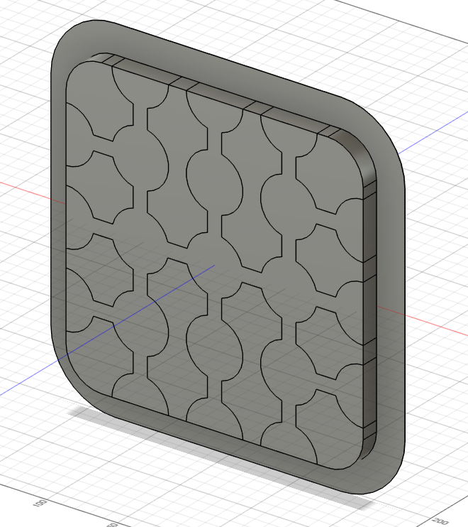
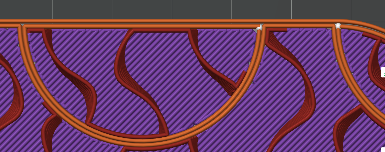
the idea is to break up any long lines in the print that might lead to warping/curling by breaking the model into two parts, one nested inside the other:
I previously did this using print modifiers. This is my first time doing it by creating a nested model in fusion360 that prints as a single monolithic model, but with a lot of internal structure aimed at defeating warping/curling. I’m in the midst of printing it now:
For some reason the Arachne wall generator complains randomly about possible collisions, so I’m using the Classic wall generator instead, which doesn’t seem to mind. Not sure as to why there’s a difference.
When it comes to removing the brim, I make a coarse first pass with a regular deburring tool to get the bulk of it off, and then I use a ceramic blade to remove the remainder. The ceramic blade avoids gouging.
which you then export. When you import it into Bambulab slicer, it imports as a single object. Position it where you want it printed, then do a “split” to break it into the two objects, which remain in position and are then ready for printing. Despite being separate pieces, the zero clearance means they fuse together during printing to create a monolithic piece as the final product.
When I did this with print modifiers, I would use cylinder print modifiers to get the circles and not worry about connecting them, but that left me with 21 separate cylinders to manage, whereas this way I can manage them all as a single unit because they are connected. The pieces of the negative image are connected via the brim. In this way, there are only two pieces in total to manage.
The next step for me will be using a similar technique to embed CF prints inside non-CF enclosing material for the purpose of making them safe to handle without worrying about the carbon fibers sticking into skin or getting inhaled, etc. But that will be a topic for a different thread, although one could also use CF embedded in this way to stiffen a print and provide further guarantee against warping/curling.
What happens if you karate punch that plate in the middle? Or flex it? Any signs that the two-body unibody might come unfused? I imagine its fine, its basically invoking multicolor printing loop seperation logic, but not switching. And those tend to fuse well.
When I tried the same thing without the brim (actually a 1mm wide brim so the whole thing would hold together as before, but basically a de minimis brim in practical terms), I still got some warping. Not a large amount, but a noticeable amount. So, it seems to require both–the brim and the chop job–at least in this instance.
My original theory was that it would be sufficient, which is what lead me to try it without the CAD integrated brim.
There may have been other complicating factors also, so I should probably try it again.
Regardless, I don’t know of anything that works better than this appears to, based on the prints I’ve done so far.
Mostly not, though I did have one instance where that occured when I confused one PETG filament with another and ended up printing at too high a flow rate for the one I used. I wouldn’t necessarily read a lot into that though, given the circumstances of its occurance.
Maybe more to the point: is it weaker? Maybe, though perhaps that can be overcome by a more carefully crafted internal design. On the other hand, it might actually be stronger. This was just version 1 for me, to test the general idea, so I’m not sure one way or the other.
Right now the biggest downside I can atest to is that it takes longer to print. However, not longer than one or more failed prints in a row before getting a non-failed print. I’m OK with the extra print time if it delivers more of a guaranteed result.
It loses its asthetic if, like a lot of people, the goal is a nice smooth printed surface. However, It might be that this could serve as the underlying skeleton, and a nice smooth exterior could be printed over that. I haven’t tried that yet. I don’t know whether doing so would negate the anti-warping of the underlying skeleton or not. My guess is probably not, but I haven’t tested that at all, let alone enough to be sure.
Yeah thats what I’m sayin, give it the ol’ karate punch. Maybe you get a feeling that it is stronger. Its basically a preengineered 2nd dimension of support ribs in there
The one case that seemed weak had only 8% infill (because I was in a hurry), so it was likely that. At higher infills it has seemed pretty solid. Whether more or less karate chop proof I’m not sure. On its face, I would think it would be stronger, not weaker.
I did notice one weird thing, though, which is that on the initial layer the Bambulab slicer inserts a gap between the walls of the two pieces. It doesn’t do that on the subsequent layers, and I don’t understand why it is doing it. I also haven’t decided whether it’s a bug or a feature in terms of anti-warp. Maybe somebody here can shed some light on that?
Anyway, getting back to smoothness: I just now generated a smaller model just to test the idea of printing a shell around the skeleton in order to get back to the ever highly sought after smooth exterior:
On the right is skeleton only, which is a simplified version of the .3mf I posted above, and on the left is the same skeleton, but with a smooth shell over it. According to the sliced result, it should indeed be smooth all across the visible surface, though not on the bottom initial layer because of what I suspect is some kind of Bambulab slicing glitch that separates the walls between distinct objects (as I mentioned above):
When my H2D frees up from the current printing queue, I’ll run the test to see for sure. If there’s any interest, I’ll post the result.
This is what I want to do anyway for printing shells of non-CF material over CF prints in order to encapsulate them, so it will do double duty as a first step in that direction also.
In any case, although the method is different, this approach is overall very much congruent with Bambulab’s second strategy for avoiding warping, which it articulates as:
I traced the initial layer gap between walls to two factors:
Elephant foot setting. Reducing it to zero helped close the gap. This nearly solved it, except for #2 below.
The slicer seems to allocate space for the bow-ties used in gap filling on the initial layer. Not sure yet how to disable that. I can’t seem to turn-off gap filling either as a workaround, let alone doing it only on the first layer.
So, some improvement, but so far that’s as far as I’ve gotten. All this in Bambu Studio. Maybe Orca Slicer might offer an escape. I’ll try printing it. Maybe what remains will make little difference, or maybe it will just flow together anyway with the elephant foot compensation disabled.
Hmmm… Looks as though that bow-tie gap persists in subsequent layers also:
So, I gather some other factor is in play. On the other hand, it does look like there’s some kind of setback operating when there is a seam, because in the same area where there is no seam, there is no gap between the walls, as illustrated by:
[Edit 2: Watching it print…. It’s exactly like the preview, even with elephant foot disabled. True WYSIWIG. Maybe it’s because I use a tuned initial layer flow rate, so maybe that effectively renders the elephant foot compensation irrelevant.
The one on the left represents the version 1 design style, which I’ll refer to as “skeletal”. The one on the right is just a thin skin of a single 0.8mm wall and two 0.2mm added layers, which I’ll refer to as “epidermis”–because it has a thin skin on it. Even just that thin veneer radically improves the appearance, and, in answer to @Bullock’s question, it feels far more sturdy and karate-chop proof than the purely skeletal one on the left, as you would perhaps expect from even educated guess alone.
Looks as though I need to recalibrate the non-initial layer flow rate to fit this particular PETG filament, and then it will look even better, and be even stronger, regardless of whether skeletal or epidermis. It was originally tuned for a grey filament, same brand, but I guess either the white color or other batch differences or perhaps even change in formulation caused some drift in flow rate away from the original calibration on grey.
Without going completely overboard, I thought it would be worthwhile to design a “guaranteed warp” object, test it to confirm that it indeed warps, and then apply the method in this thread to see whether it prevents the warp. However, I don’t want to go completely overboard, to the point of creating unrealistic conditions that maybe nothing could solve–like suddenly blowing a cold breeze over the print halfway through the printing, or placing it so close to an edge that the non-uniformity in heat would create stresses. Those are also obvious things one would normally strive to avoid, so not so relevant for everyday prints.
My initial thought was maybe just a long skinny print with sharp corners, such as maybe this:
Being skinny, it would have minimal hold-down power to resist the curling force generated by the long straight walls. So, I’m thinking it might be a good candidate. I could maybe make it taller, to stack the curling forces further, though maybe it wouldn’t be needed.
Anyone have any suggestions/recommendations on what would be a good test object and/or test conditions? The ideal would be something that adhere’s to all the anti-warp suggestions put out in Bambulab’s recent memo, but which warps anyway (if there is such a thing).
Reporting back: The solution to the wall gap problem turned out to be ridiculously easy. In Bambulab Studio slicer, simply Split into Parts instead of Split into Objects. Problem solved.
Using Split Into Parts maintains the relative position of parts, so I can now get a perfectly smooth bottom as well. It was the missing piece, so obvious in retrospect.